
Why Earthing Systems Are the Backbone of Electrical Safety: An Engineering Deep-Dive
From fault current dissipation to step & touch potential mitigation — what every design engineer must know.

1. Introduction: The Critical Role of Earthing in Modern Power Systems
In any electrical installation—from a 415V commercial distribution board to a 400kV gas-insulated substation (GIS)—the earthing (grounding) system is the single most critical safety mechanism. While circuit breakers, protective relays, and fuses detect and isolate abnormal conditions, the earthing grid provides the physical path of lowest impedance to channel dangerous fault currents safely into the mass of the earth.
When an insulation breakdown occurs, the metallic enclosures of transformers, switchgear, motors, and cable trays become energized at phase voltage. Without an engineered grounding system, any human being who touches the faulty enclosure becomes the primary return path for the fault current, resulting in severe ventricular fibrillation or fatal electrocution.
Beyond human protection, modern industrial facilities house high-density distributed control systems (DCS), programmable logic controllers (PLCs), and variable frequency drives (VFDs). These microelectronic components operate at low signal voltages (0–10V / 4–20mA) and are exceptionally susceptible to common-mode voltage noise, electromagnetic interference (EMI), and ground potential rise (GPR). A low-impedance equipotential grounding system is essential to prevent false tripping and hardware damage.
2. Fundamental Physics: Touch, Step, and Mesh Potentials
To understand why simple earthing rods are insufficient for complex facilities, electrical engineers must analyze the voltage gradients that appear on the soil surface during a ground fault.
          Fault Current (If)
                 │
                 ▼
         ┌───────────────┐
         │ Ground Rod /  │
         │ Earth Grid    │
         └───┬───────┬───┘
             │       │
    ~~~~~~~~~▼~~~~~~~▼~~~~~~~~ Soil Surface
       (V_mesh)     (V_touch)
          ▲             ▲
          │             │
        Person        Person
       Standing      Touching Frame
A. Touch Voltage (E_touch)
Touch voltage is the potential difference between a grounded metallic structure (accessible to a standing person) and a point on the ground surface separated by a horizontal distance equal to normal maximum reach (typically 1.0 meter). If E_touch exceeds the threshold defined by IEEE Standard 80 or IEC 60479-1, current passing through the hand-to-feet path can be fatal within tens of milliseconds.
Where:
B. Step Voltage (E_step)
Step voltage represents the potential difference between the two feet of a person standing 1.0 meter apart on the ground surface without touching any grounded structure. This occurs when concentric voltage gradients ripple outward from the fault point.
C. Ground Potential Rise (GPR)
GPR is the maximum electrical potential that a substation grounding grid may attain relative to a distant grounding point assumed to be at the potential of remote earth. It is calculated as:
Where I_G is the portion of fault current that flows into the earth grid, and R_g is the total resistance of the earth grid.
3. Governing International & Indian Standards
Designing an earthing system requires strict compliance with statutory codes:
| Standard | Organization | Scope & Key Mandate |
|---|---|---|
| IS 3043:2018 | Bureau of Indian Standards | Code of Practice for Earthing across residential, commercial, and industrial facilities. |
| IEEE Std 80:2013 | IEEE Power & Energy Society | Guide for Safety in AC Substation Grounding (determines permissible step/touch voltages). |
| IEC 60364-5-54 | International Electrotechnical Commission | Low-voltage electrical installations: Selection and erection of electrical equipment — Earthing arrangements. |
| IEC 62561 Series | International Electrotechnical Commission | Lightning Protection System Components (LPSC) — Requirements for earth electrodes and compounds. |
| CEA Regulations 2010 | Central Electricity Authority (India) | Measures relating to safety and electric supply: Maximum allowable earth resistance limits. |
4. Soil Resistivity: The Foundation of Grounding Design
Soil is rarely uniform; it comprises stratified layers of topsoil, clay, sand, gravel, and bedrock. Measuring soil resistivity using the Wenner 4-Pin Method (ASTM G57 / IS 3043) is an indispensable prerequisite to sizing earthing electrodes.
       Current Meter                     Voltmeter
           [ A ]                           [ V ]
             │                               │
     C1 ─────┴───── P1 ───────────── P2 ─────┴───── C2
     │              │                │              │
    ═╪══════════════╪════════════════╪══════════════╪═ Ground Level
     │◄──────a─────►│◄───────a──────►│◄──────a─────►│
The apparent soil resistivity ρ at depth a is calculated as:
Where:
Soil Types and Typical Resistivity Values in India:
In high-resistivity rocky soils, driving conventional GI pipes is physically impossible or results in unacceptably high resistance (> 20 Ohms). Here, Chemical Earthing Electrodes surrounded by Earth Enhancement Compounds (BFC / EEC) are mandatory to artificially expand the conductive diameter and achieve < 1.0 Ω.
5. Maintenance and Diagnostic Testing Checklist
An earthing system is buried underground and exposed to constant moisture, seasonal temperature fluctuations, chemical fertilizers, and stray DC currents. A rigorous lifecycle testing program must include:
6. Summary: Key Takeaways for Electrical Consultants
Designing an Earthing or Lightning Protection System?
Connect with Sprexo International's senior electrical engineers for soil resistivity analysis, IEEE 80 / IS 3043 grid sizing, BOQ estimation, and turnkey project supply.
Related Technical Publications
 Materials & Specs
Types of Earthing Electrodes: A Practical Selection & Sizing Guide
 Electrical Safety
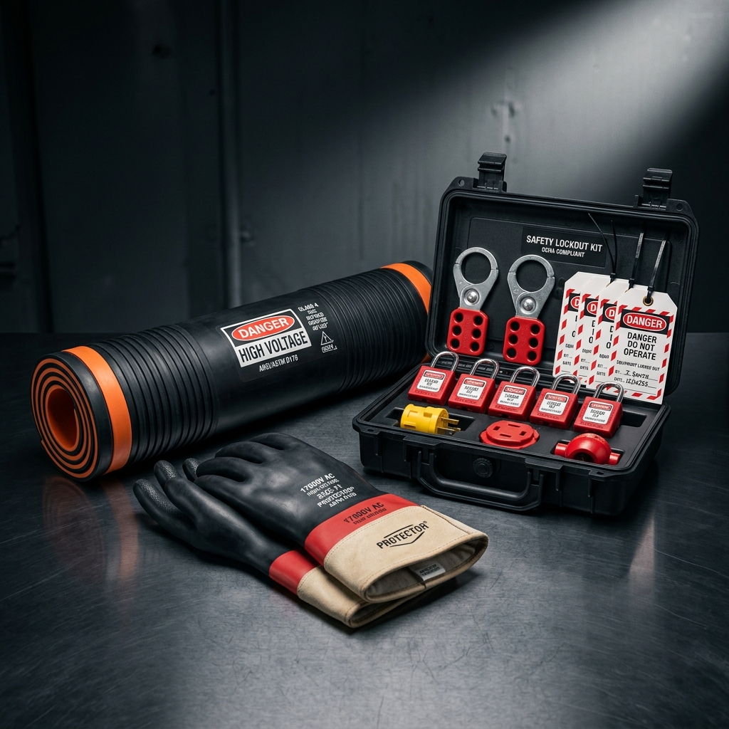
Essential Electrical Safety Equipment for High-Voltage Switchgear Rooms
 Lightning Protection