
Conventional vs. Early Streamer Emission (ESE) Lightning Protection: What's the Difference?
A rigorous engineering breakdown of Franklin rods, Faraday cages, and ESE technology under IEC 62305 & NF C 17-102.
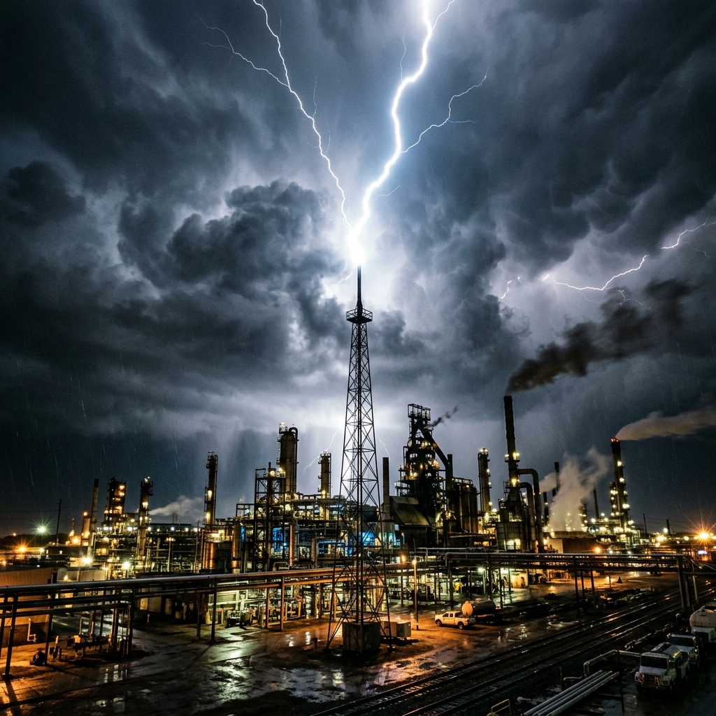
1. The Physics of a Lightning Strike
A cloud-to-ground lightning flash begins with a downward stepped leader carrying tens of coulombs of electrical charge. As the stepped leader approaches within 50 to 100 meters of the earth, the intense electric field (> 10 kV/m) induces upward connecting streamers from sharp grounded structures on the surface.
The first upward streamer that makes contact with the descending leader determines the strike attachment point, releasing peak impulse currents ranging from 30,000 to 200,000 Amperes with risetimes as steep as 1 to 2 microseconds.
An engineered Lightning Protection System (LPS) has two objectives:
2. Conventional Lightning Protection: The Rolling Sphere & Faraday Mesh (IEC 62305)
Standard IEC 62305 defines conventional passive protection using Franklin rods, horizontal roof conductors, and down-conductors forming a Faraday cage around the structure.
       Rolling Sphere (Radius R)
               ╭─────────╮
             ╭─╯         ╰─╮
            ╭╯             ╰╮
           ╭╯   Franklin    ╰╮
           │      Rod        │
       ────┴───────▲─────────┴──── Roof Surface
The protection zone is calculated using the imaginary Rolling Sphere Method:
Limitation: For large, sprawling structures (airports, industrial refineries, solar farms), installing hundreds of passive air terminals and a dense roof mesh incurs massive structural weight, aesthetic compromises, and high installation costs.
3. Early Streamer Emission (ESE) Technology (NF C 17-102 / UNE 21186)
An Early Streamer Emission (ESE) air terminal incorporates an internal high-voltage pulse triggering mechanism. When a thundercloud creates a strong pre-strike electric field, the ESE unit generates an early upward leader with an advance triggering time ($\Delta T$) of 25 to 60 microseconds before conventional passive rods can react.
Formula for ESE Protection Radius (R_p):
Where:
4. Detailed Technology Comparison
| Feature | Conventional Faraday Cage (IEC 62305) | ESE Lightning Terminal (NF C 17-102) |
|---|---|---|
| Interception Method | Passive metallic air rods & roof mesh | Active ionization with advance time Δ T |
| Coverage Area | Small localized zone per rod | Massive radius (up to 120 meters per unit) |
| Roof Impact | Heavy network of copper/GI strips | Single or dual centralized masts |
| Down-Conductors | Multiple perimeter lines (every 10-20m) | Minimum 2 dedicated down-conductors |
| Maintenance | Regular joint tightening & visual check | Annual electronic pulse emission test |
| Best Suited For | Compact residential, historical monuments | High-rise towers, industrial parks, solar farms |
5. Critical Down-Conductor & Earthing Integration
An ESE terminal is only as good as its earthing termination:
Designing an Earthing or Lightning Protection System?
Connect with Sprexo International's senior electrical engineers for soil resistivity analysis, IEEE 80 / IS 3043 grid sizing, BOQ estimation, and turnkey project supply.
Related Technical Publications
 Earthing Engineering
Why Earthing Systems Are the Backbone of Electrical Safety: An Engineering Deep-Dive
 Materials & Specs
Types of Earthing Electrodes: A Practical Selection & Sizing Guide
 Electrical Safety