
Industrial Grounding Grid Design for Substations & Heavy Process Plants
Applying IEEE 80-2013 and IS 3043 to design robust equipotential grounding grids.
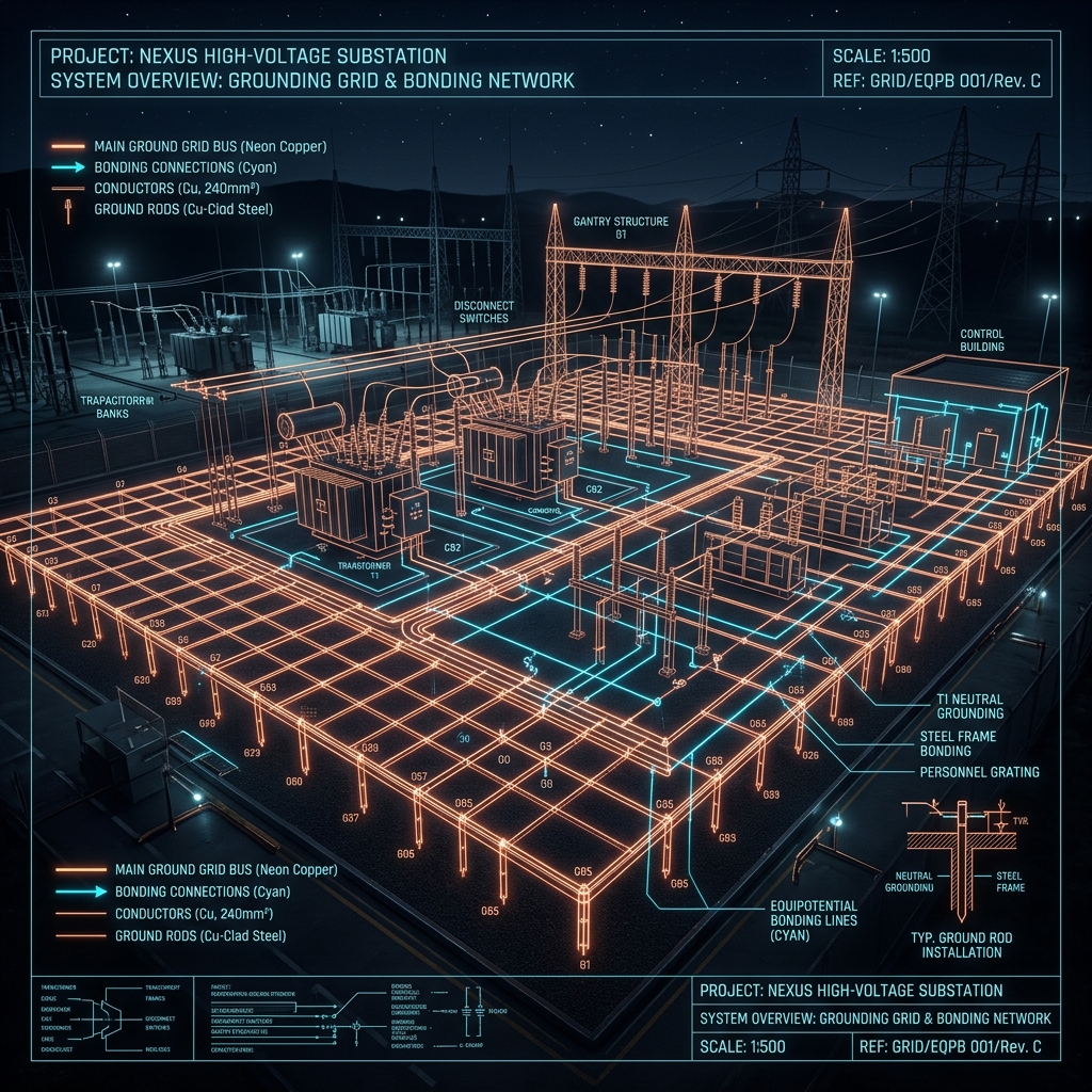
1. Fundamentals of Substation Grounding Grid Design
In high-voltage substations and heavy industrial complexes, fault currents can reach 40kA to 63kA during line-to-ground faults. A simple radial rod earthing system cannot handle these immense energy levels.
The engineering solution is an interconnected equipotential grounding grid (mesh) buried 0.5m to 1.0m beneath the entire yard surface, supplemented by deep vertical ground rods at perimeter corners.
2. Step-by-Step IEEE Standard 80 Design Methodology
  [ Step 1: Soil Resistivity Profile (Wenner 4-Pin) ]
                          │
  [ Step 2: Conductor Sizing for Maximum Fault Current (3s) ]
                          │
  [ Step 3: Compute Permissible Touch & Step Voltages ]
                          │
  [ Step 4: Initial Grid Mesh Layout & Total Conductor Length ]
                          │
  [ Step 5: Calculate Grid Resistance (Rg) & GPR ]
                          │
  [ Step 6: Verify Mesh & Step Voltages < Permissible Limits ]
                          │
        ┌─────────────────┴─────────────────┐
     [ Safe ]                           [ Unsafe ]
        │                                   │
  [ Finalize Design ]          [ Reduce Mesh Spacing / Add Rods ]
3. Conductor Cross-Section Sizing Formula
The minimum cross-sectional area A_kcmil of the grounding conductor to withstand the thermal heat of a short circuit is governed by the Onderdonk / IEEE 80 equation:
Where:
Key Takeaway: Because exothermic welded joints can withstand up to 1083°C, they allow a significantly smaller conductor cross-section compared to bolted clamps, saving thousands of kilograms of copper in large substation projects.
4. Exothermic Welding vs. Mechanical Bolted Clamps
Exothermic welding is a high-temperature aluminothermic reduction reaction (2Al + 3CuO → 3Cu + Al_2O_3 + Heat) carried out inside a precision-machined graphite mold.
| Evaluation Metric | Exothermic Welded Joint | Mechanical Bolted Clamp |
|---|---|---|
| Electrical Resistance | Equal to or lower than original conductor | Higher resistance due to surface contact interface |
| Corrosion Susceptibility | Zero corrosion (Molecular copper bond) | High (Galvanic oxidation & moisture ingress) |
| Current Carrying Capacity | Will not melt before conductor melts | Can loosen, arc, or burn out under fault |
| Mechanical Strength | Permanent molecular weld | Subject to vibration loosening and torque relaxation |
| Inspection Need | Permanent zero maintenance | Requires periodic re-torquing and testing |
5. Crushed Rock (Surfacing Layer) Specification
IEEE 80 mandates spreading a 100mm to 150mm thick layer of clean, washed crushed stone/gravel across the entire substation yard.
Designing an Earthing or Lightning Protection System?
Connect with Sprexo International's senior electrical engineers for soil resistivity analysis, IEEE 80 / IS 3043 grid sizing, BOQ estimation, and turnkey project supply.
Related Technical Publications
 Earthing Engineering
Why Earthing Systems Are the Backbone of Electrical Safety: An Engineering Deep-Dive
 Materials & Specs
Types of Earthing Electrodes: A Practical Selection & Sizing Guide
 Electrical Safety